


Installing DCC in an American Models Amtrak EMD F40PH
By Michael Greene
Please be patient - there are 4 pictures on this page to load for viewing!
Like so many other S scale engines, there are a large number of choices when installing a NMRA DCC compatible decoder in the EMD F40PH (Amtrak) from American Models. This article describes the conversion of a DC version of this locomotive. If you have an AC version with an E-unit, you'll need to remove that before starting. This is a relatively easy locomotive to convert to DCC because of the amount of space available in the locomotive.
One of the first steps in selecting a DCC decoder is to measure both the operating current and the stall current of the particular locomotive. In our tests, the American Models F40PH has an operating (wheels slipping) current of 0.7A @14VDC and a stall current of 1.6A @14VDC.
In this article we will show you the installation of two different decoders. (Unfortunately this conversion was finished before we took any pictures, so we're missing a couple of the step by step pictures. But since it is an easy conversion, we don't think you'll have much difficulty following the steps without pictures.)
First let's look at the option to use a very small decoder. The first DCC installation I did in this locomotive used a Digitrax DN93FX decoder. Digitrax brought this decoder to the market to meet the needs of N scale and small HO scale engines. This decoder has been retired by Digitrax and replaced by the Digitrax DN142. The specific decoder is not critical, but as you can see in the next picture, in S scale you can put the decoder almost anywhere. The DN142 decoder is rated at 1 amp continuous motor current (1.5A peak), more than adequate for the motor in the F40PH, and is only 0.36" x 1.0"x 0.18" (0.92cm x 2.5cm x 0.46cm) . You can find more information on this decoder on the Digitrax web site by following the link above.
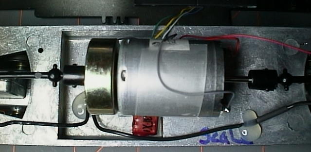
You'll note in the picture above that we placed decoder in the cavity below the motor. Obviously given it's size, you can place it in a number of different locations. Three things to keep in mind:
- Make sure that wherever you place a decoder that you attach it so that it cannot move around. I use a small piece 3M brand double sided 1/2" wide foam tape to mount my decoders.
- Placing the decoder with foam tape directly on the motor is not necessarily an incorrect thing to do, as long as the electronic parts cannot touch the motor or any other metal part. Sometimes mounting right on top of the motor is the perfect place. But if possible I prefer to place my decoders elsewhere since it means I spread out the heat that is generated by both the decoder and the motor.
- Wherever you place the decoder, make sure you pay careful attention to wire placement. I prefer to tape my wires in place, or use a dab of hot glue. I also prefer to keep the wires relatively short, so that there is not a lot of excess wire in the locomotive.
The installation of this decoder is very simple. The F40PH does not have an NMRA DCC socket built in it from the manufacturer, but it is a very easy locomotive in which to install a decoder because the mechanism is so open. Basically the steps to install a decoder in this locomotive are:
- disconnect the wires at the motor which connect the power pickups to the motor
- connect power pickups on the locomotive to the rail pickup leads on the decoder - remember to connect the right and left rails to the correct leads on the decoder so that the locomotive will move in the correct direction if run on a normal DC powered layout
- connect the motor to the motor leads on the decoder
- wire the light to the decoder
Note that one of the IMPORTANT things to do when installing a decoder in this locomotive is to REPLACE the light bulb supplied by the manufacturer with a much lower current draw bulb. The light bulb supplied by the manufacturer is a high current draw bulb, and use of it with a decoder WILL burn out the decoder function lead. We have had good luck using a Miniatronics 16VDC bulb which draws a mere 30mA. These are available in packages of 10 (#18-016-10) or 20 (#18-016-20) at a very reasonable price. You can simply remove the entire light bracket & bulb from the chassis, and replace it with the Miniatronics bulb, taping the bulb in place in the shell with electrical tape, or using hot glue. Some folks prefer to use a small piece of brass tubing to surround the bulb to dissipate the heat. The instruction sheet supplied with your decoder will have more information on an appropriate bulb or lLED and its connection.
A while after installing the Digitrax DN93FX, Digitrax started releasing their "plug-n-play" line of decoders for the HO locomotive market. After looking at one of them, I decided that this type of decoder is good fit for many S scale locomotives. It has all the components on a single side of the circuit board. And although I would not be able to use it as "plug-n-play", the layout of the decoder made installation by soldered connection very easy. So I decided to give one a try. About the same time I was interested in a decoder installation to show off some of the other capabilities of DCC decoders. I was thinking about the Amtrak locomotive and how Amtrak's F40PH's had alternating strobes at the corners of the top of the cab. Since the Digitrax "plug-n-play" decoders also have special lighting effects (Digitrax calls them FX) built right in, I decided to remove the Digitrax DN93FX and replace it with a Digitrax DH150A, and at the same time add some more lighting to the locomotive.
The Digitrax DH150A decoder is designed as a light board replacement for certain Atlas HO engines. But it very easy to install in S, with very nice pads for soldering wires. It is rated by the manufacturer at 1.5A continuous motor draw, more than adequate for the motor in the F40PH. In this specific case we are using the functions and FX lighting effects to support working alternating strobes on the loco, in addition to the normal head and tail lights. You can find more information on this decoder by following the link above.
We will need to make minor modifications to the shell of the
F40PH. For all of our lighting work, including the strobes, we used the Miniatronics
16VDC 30ma bulbs mentioned above. In the next picture you can see the two small
holes we drilled in the roof of the cab, and the Miniatronics bulbs coming through.
We made them
just the size for the Miniatronics bulbs to push through, and then used a bit
of hot glue inside the shell to hold them in place. After putting the bulbs
in place, along with the hot glue, we put a piece of black electrical tape over
them inside the shell to keep the light from escaping to other places inside
the cab. While we were installing bulbs, we installed two bulbs for the front
headlight (required drilling an extra hole), and installed two bulbs for the
rear lights. In the next photo you can see the two headlights and strobes.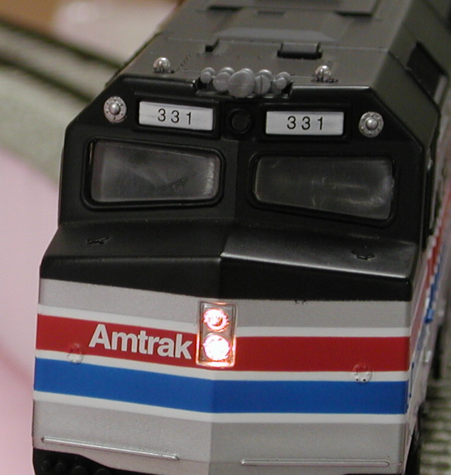
The next photo shows a close-up of the Digitrax DH150A decoder
as it was wired in the locomotive.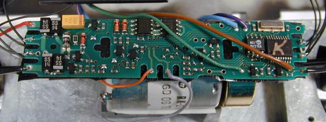
Notice
the four small tabs/protrusions on each end of the decoder. You can solder directly
to the these tabs. Refer the decoder manual for details, but basically the ones
at the corners are for rail pickup, and what I did to install this decoder was:
- Put a small piece of double stick foam tape on the back of the decoder, and stick the decoder to the top of the motor. Check the Digitrax decoder manual to see which end of the decoder has the connection points for the front headlight. Make sure this end is pointed towards the front of the locomotive before you stick the decoder on the motor!
- Solder the pickup on each truck from the left rail to appropriate solder point at each end of the decoder
- Solder the pickup on each truck from the right rail to appropriate solder point at each end of the decoder
- Notice in the photo the small orange and gray wires soldered to the tabs on the side of the decoder. These are the motor connection points. I used short pieces of the appropriate color wires (saved from other decoder installations where I had cut them shorter) to connect from the decoder to the appropriate points on the motor.
- The two inside tabs on each end of the decoder are for the front or rear lights (front light at one end, read at the other). You'll note wires soldered to them in the picture.
- Also notice the Green, Violet, and Blue wires. These are the extra functions (F1 and F2) that are used to connect the strobe bulbs.
When you are all finished with your installation, I recommend the use of some black electrical tape to tape down any loose wires so that they will not interfere with the mechanism when running.
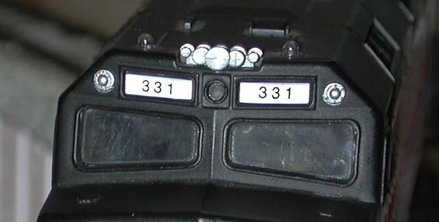
Finally you need to take your locomotive to the DCC programming track. You can set the address to what you would like it to be. I set mine to 331, the road number. You also need to program the CV's to create the alternating strobe effect. For this decoder, program CV51=36 and CV52=52 (these are the decimal values). Once you've done this you can put the loco on the mainline, turn on F1 and F2 and you will have your alternating strobes. And remember that if you're using a Digitrax throttle, the F2 key may be set as a "momentary on" function. If so you'll need to consult you cab manual to see how to lock F2 on.
Conclusion
I hope these photos will make it easier for you if you are interested in installing DCC in your American Models F40PH, and give you an idea or two for enhancing the F40PH.
Good luck with your installation!
Michael
Copyright © 2002-2006, C. M. Greene. All rights reserved.
webmaster