
Installing DCC in Putt Trains' Thomas
By Michael Greene
Click on any of the pictures for a larger view
 Installing
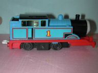
a DCC decoder in the S gauge Thomas the Tank engine sold by Putt
Trains is an easy one night project.
Start by removing the shell of this locomotive - just remove one screw and some double stick foam tape holding the mechanism in the shell. After removing the screw, I removed & discarded all the foam tape, and cleaned up the tape spots, since I planned to installed new foam tape at the end of the project.
 The
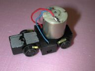
first step in my installation was to change the wiring in the standard
locomotive. I had noticed when I first ran the locomotive on DC
that it ran in the opposite direction as the rest of my locomotives.
So the first thing I did was swap the wires at the point where the
wires attached to the motor. You can see the modified wiring in the photo at the
left. Once I made this change and tested it, I was ready to install
the DCC decoder.
As I was removing the shell from the locomotive, I noticed that there was no room to install the decoder above the motor, but there was a reasonable amount of room in boiler. Since I only needed a very basic DCC decoder (this Thomas does not need a lot of functions since he has no lights, his eyes don't move, and I was not adding sound), I selected an old Digitrax DN140 N scale decoder that I had in excess stock. This is a 1amp decoder, but more importantly it was a relatively small decoder that would fit in the boiler quite easily.
The installation was simple. First I cut all the decoder wires to about 2 inches long, so that I would not have a lot of excess wire to put somewhere. Then I removed the red pickup wire from the motor terminal to which it was soldered, and connected it (red pickup wire) to the red wire on the decoder. Don't forget to put a piece of shrink tubing on the one of the wires before soldering, in order that can be slipped over the solder connection and shrunk afterwards to provide insulation. Then solder the decoder's orange wire to the motor terminal where the red pickup wire had been soldered.
 Now
repeat the process, removing the blue pickup wire from the motor,
soldering it to the black wire on the decoder, and soldering the
decoder's gray wire the motor terminal where the blue wire had been.
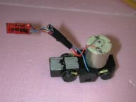
And slip on the shrink tubing. Next I used a piece of electrical tape
to neatly tape up all the loose wires. You can see the completed
installation in the photo at the right. Using this approach allowed
me to fold the decoder back along side the black electrical tape and slide
it in the boiler as I inserted the mechanism back in the shell.
Don't forgot to put on some new foam tape before inserting the mechanism!
Replace the single screw and the project is finished.
I set the address on mine to the Thomas's engine number (1) since I have no other engine with that number on my roster. Also I did not tape the decoder to the shell, just in case I should have to remove it later for any repair work.
 Even
though the project is finished, I'm now considering adding some sounds.
I recall having a small Thomas sound toy that produces a few different
sounds when different buttons are pressed. If I can find it in the
house (a big IF!), I may disassemble it and see if it could be
inserted in the boiler along with a small speaker, and controlled by
one of the function wires on the decoder. But that is a project
for another day! In the meantime, I'll just enjoy watching the kids
eyes light up when they see Thomas, Annie & Clarabel working
on my S gauge layout! Now the only question left to ask is when
Percy will come for a visit?
Enjoy!
Copyright © 2002-2006, C. M. Greene. All rights reserved.
webmaster


