


Installing DCC & Sound in the S Helper Service SW-1
By Michael Greene & Bill Clark
Please be patient - there are 10 pictures on this page to load for viewing!
The EMD SW-1's shipped in March 2000 by S Helper Service are nicely set up to make installation of a DCC decoder very simple. The locomotive comes from the factory with a NMRA DCC socket, and conversion to DCC involves four simple steps (all documented in the excellent instruction manual that ships with the locomotive):
- Remove shell
- Unplug and remove E-unit
- Plug in a DCC decoder with the appropriate DCC plug (these are available from most of the major DCC decoder manufacturers)
- Replace shell & test
It couldn't be any easier!
Installing DCC + Sound
We were interested in our SW-1's having both DCC and sound. So Don Thompson of S Helper Service challenged us to install both DCC and sound in the available space. We eagerly accepted, and set a goal to have a pair of them running with sound on the Bristol Club's modular layout at the huge railroad show in Springfield, MA the first weekend of February 2000.
We knew that space would be tight, particularly since the SW-1 shell is almost an inch shorter in length than it's brother the SW9/1200. And of course we wanted sound in the loco, not in a trailing sound car. And finally we preferred to have our sound without having to make modifications to the shell, such as drilling fine holes in grill work to allow sound to escape.
In order to accomplish this task we decided to use the following:
-
Lenz
LE040 decoder - this decoder would be used for motor control. We
prefer decoders with back-EMF support (Lenz calls this load compensation)
because they offer finer slow speed control, and we also needed a very small
decoder because there is not a lot of extra room. This decoder is rated at
0.7amps (more than adequate for the motor in the SW-1), has an NMRA
Conformance Seal, and is only 0.63"(L) x 0.57"(w) x 0 .18"(H)
(or L 16.0 x W 14.5 x H 4.5 mm). You can find more information on this decoder on
the Lenz web site by following the link above.
13 Apr 2003 Update: If you cannot locate a Lenz LE040, you might try substituting one of these decoders: Lenz LE0511, Lenz LE0521W (aka LE010), Digitrax DZ143, TCS M1, or NCE N12SR (the latter two very recently announced). While we have not tried these specific decoders in this installation, they all have approximately the physical measurements as the LE040 we used. Size is key because or the limited space available, given that we're installing two decoders and a speaker. Current rating is not an issue as the SW-1 draws very little. Especially for switchers, we do like the slow speed operation provided by decoders with back EMF support.
- SoundTraxx DSX diesel sound decoder - this decoder would be used for sound. This decoder has very easy connections to the rail pickups and to the speaker. It is also relatively small at 1.25" x .625" x .25". We chose Leslie horns since we liked the sound, but choose one based on your preferences (prototype practice, pleasing sound, etc.). (A Wabco single chime will be the appropriate choice for many prototypes.)
- and of course a speaker with enclosure.
Once installed, the decoders' addresses would be set up to allow them to operate as a single unit on the layout.
Each of us used slightly different installation techniques with these components. Our approaches are described below. As with most DCC installations there is not one ideal installation. But there are certainly correct and incorrect ways (Letting the smoke out of the decoder is an incorrect installation! :-) If you intend to install DCC+sound in your loco, please read completely through these instructions one or more times before starting the installation so that you have a complete understanding.
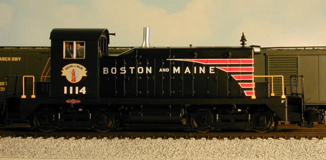
Here's a picture of the SW-1 before we started the conversion. The picture after conversion looks exactly the same as we made NO exterior modifications to the shell or locomotive.
In order to get started we had to following the normal process outlined above: remove the shell, and then unplug and remove the e-unit. In this next picture you can see the insides of an unmodified SW-1. Note inside the shell you have the E-unit to the left and yellowish colored spring assembly to the right. And of course the PCB on the chassis.
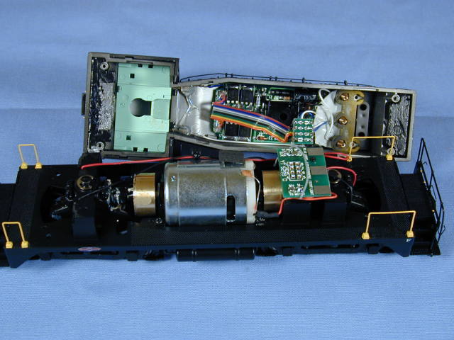
TIP: to remove the small assembly with springs that provides the contacts between the PCB with the socket and the lights in the shell, use a pair of needle nose pliers, grab the assembly with springs in the middle, and rock it back and forth as you gently extract it off the posts. It's a tight fit, but will come out!
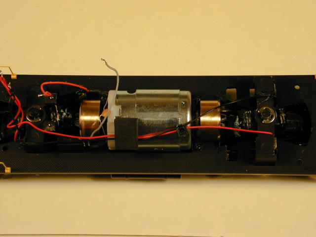
Here we have removed the PCB where the E-unit or DCC decoder plugs in to make more room for the speaker:
Here are the specific steps Michael used to prepare the locomotive for the installation.
- Unplug the E-unit from the PCB on the chassis
- Remove the "spring assembly" inside the shell. This item has three springs on it that make contact with the PCB on the chassis. See tip above on how to remove.
- Remove E-unit (held in place by two screws)
- Remove PCB on chassis. This requires de-soldering the four connections -- a gray wire to one motor post, an orange wire to the other motor post, two red wires to right rail pickup, and two black wires to left rail pickup. Then remove the two screws holding it in place.
- Cut the white and black wires on the front light. These wires connect to the spring assembly. Leave approx 1.25" of each wire on the bulb.
- Cut the blue wire leaving approximately 1.25" on the end connected to the spring assembly.
- Cut the remaining white wire connected to the spring assembly, again leaving approximately 1.25" on the end connected to the spring assembly.
- Next Michael removed the forward light unit was removed simply to make the installation easier -- it will be reinstalled without modifications near the end of the process.
Then use a motor tool with a cut-off wheel (be sure to use eye protection) to remove the four mounting posts in the top of the shell --- two shorter mounting posts where the E-unit screws went in, and two longer mounting posts where the spring assembly wrapped around. From here on it was a little different.
Remember to use shrink tubing over all solder joints to insulate the connection!
Michael's Installation approach
Here are the specific steps Michael used in his installation:
- Solder the end of the blue wire remaining in the shell (near the front light bulb) to the black wire on the front bulb
- Solder the white wire remaining in the shell (near the front light bulb) to the white wire on the front bulb
- Carefully de-solder the white wire near the cab from the bare copper wire to the bulb in the cab. Bend the white wire back away from the bare wire a small amount. Do not remove either!
- Cut the blue, yellow, and white wires on the LE040 short (approximately 1.5" long)
- Solder the blue wire from the LE040 to the junction of the blue wire in the shell and the bare wire going to the rear bulb. This junction is near the cab, on the opposite side of the shell from the white wire you de-soldered in step 3. Be careful not to de-solder the blue wire and the bare wire in the process. Essentially you are simply adding the blue wire from the decoder to this junction.
- Solder the white wire on the LE040 to the white wire going up to the front light bulb. It connects to the end you de-soldered and bent back slightly in step 3.
- Solder the yellow wire to the bare wire going to the rear light bulb on the opposite side of the shell from the bare wire connected to the blue wire.
- Install the speaker, and connect the purple wires from the SoundTraxx DSX to the speaker per the SoundTraxx instructions. Don't forget the capacitor! And notice that it matters which purple wire from the DSX connects to the capacitor and then to the speaker. See the diagram in the DSX installation instructions.
- Shorten and solder the motor leads from the LE040 (orange & gray wires) to the matching orange and gray wires on the motor.
- Shorten and solder the rail pickup leads from both the LE040 and DSX (red and black wires) to the matching red & black wires that were de-solder from the PCB rail pickup pads.
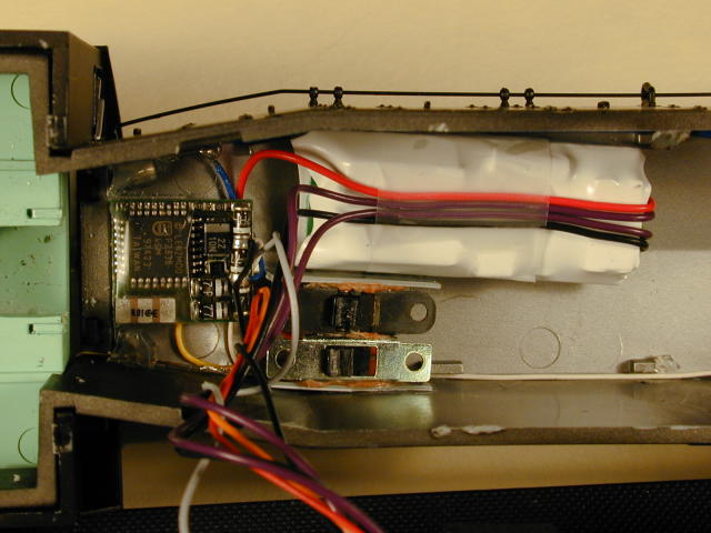
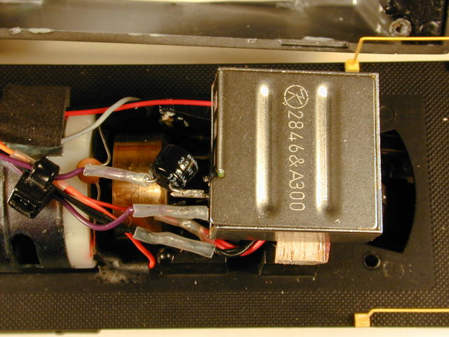
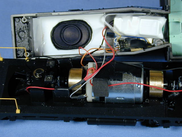
In this next picture you can see the placement of the Lenz LE040 and the SoundTraxx DSX decoders. Double-sided foam tape was used to hold them in place. Also note the two micro slide switches that were installed. Each one was installed on one of rail pickup leads on each decoder. Should a future problem occur with programming the decoders in Operations mode, these switches can be used to temporarily "cut-out" a decoder, so they can be placed on a programming track and programmed individually. Miniatronics # switches were used, along with Walthers Goo and a couple of pieces of styrene to make an assembly. Several other approaches could have been used as well to accomplish the same thing.
This next photo shows the placement of the speaker. Note it is placed in basically the same location as the PCB that was removed earlier. The exit ports for the sound are facing down, so that sound exits around the truck, and no modifications are required to the shell. The speaker used was a Pacific Fast Mail PFM-X10 Face Ported Speaker Enclosure which comes already enclosed and with a row of sound exit ports on the "face" of one side of the enclosure.
Here's a side view of the speaker mounting:

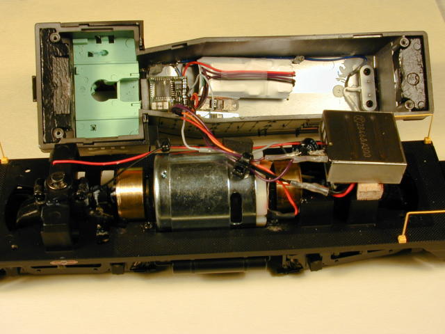
And here is the picture of the complete installation:
Bill's Installation approach
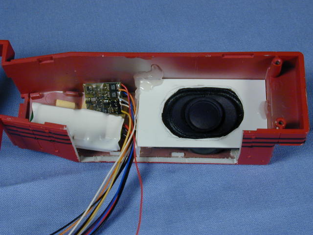
Bill used the same decoders, but used a different speaker and approach for mounting. These next pictures show Bill's installation. In this first picture we can see Bill test fitting the speaker, enclosure, and decoders, using a cut away shell. (Please don't cut your shell! S Helper Service provided this so that we could work out the details and get some photos showing the fit!) Bill used a 1.1" x 1.6" oval speaker and mounted it using two pieces of styrene, plus the shell to make up the enclosure. The speaker is available from several suppliers including SoundTraxx (#810078), Dallee Electronics (#662), and available as a part from Allied Electronics(623-2085). The speaker is actually made by Intervox and is part number S11X16VNS.
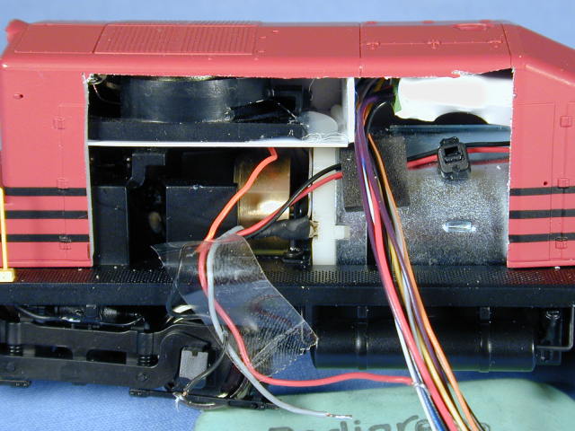
And in this next picture you can see the fit with the shell placed on the chassis. The vertical piece of styrene for the enclosure is 9/16", and the horizontal piece of styrene is cut to fit the tight in the shell, with a cutout removed for the face of the speaker.
Here is the final installation in Bill's SW-1 shell. Note again that the PCB was removed to make room for the speaker. And that the decoders were wired directly in. Bill did not add the extra switches, as he has been very pleased with programming the decoders in Operations mode.
Conclusion
We hope these photos will make it easier for you if you are interested in installing DCC plus Sound in your SW-1. We want to thank all of the folks at S Helper Service for producing this fine engine, and in particular Don Thompson for his challenge & then assistance in getting us these units in time, so that we could get the installations completed in time to run at the Feb 2000 Springfield, MA railroad show.
Good luck with your installation!
Michael & Bill
Copyright © 2002-2006, C. M. Greene. All rights reserved.
webmaster